Overview
Every connection in a CLIP circuit has a mapping that specifies which elements in the consumer object are connected to which elements in the provider object. When a connection is created, a default mapping is selected based on the dimensionality of the two end-points and as the dimensionality of the end-points is subsequently modified, the mapping is updated appropriately. In most cases this default mapping is adequate but sometimes it is necessary to specify a different mapping and this is achieved using the Connection Editor. Having changed the mapping from the default, it is no longer tied to the dimensionality of the end-points and will require manual updating. This link can be re-established by resetting the mapping to its default value.
Connection Editor Dialog
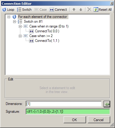
You can override the automatically generated connection mapping using the Connection Editor Dialog. This allows you to modify from the default connection mapping or to define a completely new mapping. The dialog has options to add loops, switches and cases, and to specify the connections to be made for each. The editor produces a "Signature" to be processed by the translator and this is displayed at the bottom of the dialog for advanced users.
NB. Any 'Repeat Count' specified in the Connection Properties window is not shown in the "Signature" box or the Editor, and is subsequently added around each 'ConnectTo' call.
The dialog has 4 main sections
- Action Options
- Mapping Tree
- Edit Window
- Signature
Action Options
The Action Options allows a number of signature constructs to be quickly defined


Add a loop - A loop will force the associated connection tree to be repeated a number of times

Add a switch statement - allows a sub-tree of connections to be made depending on the the switch specifier

Add a case statement - defines the sub-tree to be made if the switch specifier matches any of the case values.

Add a connection statement

Reset everything back to the default (auto-generated settings)

Delete the selected entry (delete key can be used) and all of its child entries.

Move the selected item up/down (page up/page down keys can be used)
The options available will be dependent on the current selection.
Mapping Tree
The Mapping Tree shows the current structure of the connections. This is easier to visualise than the Connection Signature.

Selecting items within the tree enables the appropriate Actions and Edit Options.
Edit Window
The edit window allows the selected item in the Signature Tree to be edited. The format of the window is dependent on the selection.
No Selection/Main element Loop Selected
ConnectTo selected - enter the element number of the object to be connected to.
As well as numerical values the special values ^n (loop index), #n (connectee element index) (where n is a value) can be used. When multi-dimensional objects are being connected a comma-separated list should be specified.

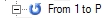
Loop selected - enter the limit of the loop as a numeric value or a macro value
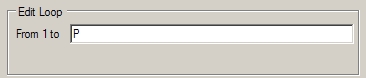
Values entered will be shown in the tree as
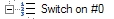
Switch selected - enter the connector element value top switch on (#0,#1...)
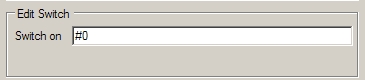
Values entered will be shown in the tree as
Case selected - enter the lower and upper values to be accepted
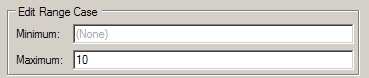
If either the minimum or maximum fields are left blank ( (none) ), the translator will omit code to test for the appropriate limits. If both are blank ( (none) ) the translator will omit both bounds tests, thus becoming a catch all (default) case.
Range cases specified in a switch are be processed in order. Thus if two ranges overlap the first will always be used. This allows less specific ranges to be applied after the more specific ones. In general a catch all remaining values (default, no min max values) is often specified as the last case. To restrict a case to a specific value, users need to specify a min and max with the same value.
Values entered are shown on the tree as
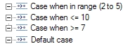
Min 2 Max 5
Min (none) Max 10
Min 7 Max (none)
Min (none) Max (none)
Signature
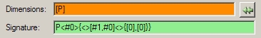
The signature area shows the current connection signature and dimension from the connection tree.
The connection signature is automatically updated as the tree is modified and will be shown in Green the signature is complete and correct. However, if there are any errors or missing entries (ie a switch with no cases) it will be shown in Red.
The dimension field shows the last known connection dimension, it is not updated automatically as it can be set by the user. However, it is compared to an automatically calculated value. If the shown dimension is the same as the calculated value or is a plausible variation of the calculated value, it is shown in White. Otherwise the dimension is shown in Red.
Pressing the  button will cause the calculated value to be displayed,
replacing any previous calculated or user input.
button will cause the calculated value to be displayed,
replacing any previous calculated or user input.
If the connection signature contains a set of switches or loops than mean that a single dimension value cannot be calculated, a value of [*] is used and the code generator will generate an access function with one argument (plus any repeat count). It is up to the user to decode the connection structure to get to the required single element number. The generated code will not generate any dimension checking logic.
Eg
switch
case 1
connect to element 1;
case 2
connect to elements 1 and 2;
...
case N
connect to elements 1..N.
In this instance there are different dimensions for each case (1, 2, N). Thus the user code must check for the connector object element number and pass the appropriate connection element number to the access function.
When no connection dimension can be calculated, any user specified connection dimension will be a plausible variation on the calculated value. To highlight this condition the dimension field will be shown in Orange. Similarly, a displayed/user specified value of [*] will also be shown in Orange IF the calculated value is NOT [*].
When the circuit is translated the dimension is compared to the calculated dimension. If the dimensions differ, a warning or error will be generated. Warnings are generated if there is a plausible mismatch, whilst errors are generated if there is an implausible/dangerous mismatch.
Eg.
Calculated Dimension User Specified Dimension Condition Comments
[*] [2][4] Warning User is assumed to know best, but dimension may not been updated after a signature change
[9] [3][3] Warning Splitting a dimension is allowable, but dimension may not have been updated
[3][3] [9] Warning Combining a dimension is allowable, but dimension may not have been updated
[4][3] [2][6] Error Splitting one dimension and combining with another is not recommended
[2][9][4] [9][8] Error Combining (or splitting) non-adjacent dimensions is not recommended
[10] [3][3] Error Dimension mismatch
[N] [2] Error Dimension mismatch
[3][4][2] [4][3][2] Error Dimension reordering is not recommended
[N][2] [N*2] Error Can only combine (or split) numeric dimensions
There are a number of conditions where it is not possible to generate a regular dimension structure from a signature. This usually occurs when there are different connection structures within switch cases, or flat loops (as opposed to nested loops) with different loop sizes or internal structures.
Examples
The dialog above shows a user defined connection for two 2-d objects.

This signature would generate the following code
for #1 in M
for #0 in N
switch ( #1 )
case 0..1:
Connect
[#1,#0] to [0,0]
case 2..M-1:
Connect
[#1,#0] to [1,1]
Note: the generated code will always generate a loop for each dimension of the connecting object, even if the signature only specifies a switch on one of the loop variables. Thus each of the inner Ns will make the same connection profile. To restrict the connections to 'a single element connecting to a single element' would require a double switch in the signature
<#1>{<1,1><#0>{<0,0>[3,4]}}
for #1 in M
for #0 in N
switch ( #1 )
case 1..1:
switch ( #0
)
case 0..0:
Connect
[#1,#0] to [3,4]
Irregular Connections
In some cases an even more advanced connection logic is required that cannot be defined by simple loops and switches. To this end Blueprint allows irregular connections to be defined via user defined macro functions.
In the following examples the an array of consumer objects only requires connections to a sub set of the provider objects (both same dimension). The first is a 1-d example, the second a 2-d example.
Example 1
The 1-d Collector is required to make a sub set of connections to the semaphore, depending on its element number.
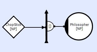
Each collector element 'n' connects to a pair of Counting Semaphores 'n' and 'n+1'. However, if 'n' is odd it must connect to element 'n' then 'n+1', if even it must connect in the opposite order 'n+1' then 'n'. When 'n+1' is greater then the number of elements, it must wrap around to element 0.

If NP is known then this connection 'could' be configured using the switch mechanism, but this could be cumbersome and prone to errors, especially if NP was to be changed. To make this connection using macros we need to generate two macro functions 'First()', 'Second()', and make connections using these.
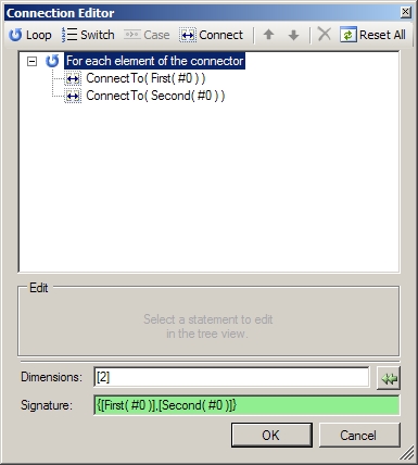
These functions can be defined in the ProjectHeader.hpp file. Each function generates a single element number.
#define NP 7
#define First( X ) ( ((X)%2) ? (X) : (((X)+1)%NP) ) // if odd
connect to X else X+1 - wrap X+1 to 0 if required
#define Second( X ) ( ((X)%2) ? (((X)+1)%NP) : (X) ) // if odd connect to
X+1 else X - wrap X+1 to 0 if required
In this example the arguments to the macros are simply the loop variable, but this not a restriction. We could have passed other parameters into the macro
Eg.
#define Next( N, X, Y ) ( ((N)==1) ? ( ((X)%2) ? (X) : ( ((X)+1) % (Y) ) ) : ( ((X)%2) ? ( ((X)+1) % (Y) ) : (X) ) )
ConnectTo( Next( 1, #0, NP ) )
ConnectTo( Next( 2, #0+1, NP/2 )
Example 2
In this 2-d grid example each collector needs to make a sub set of connections the the data store depending on the its element number.
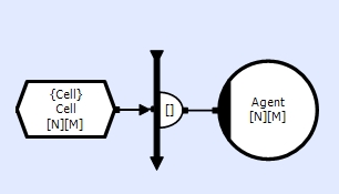
Each collector n,m connects to its 8 neighbours and its self (in a specific order).
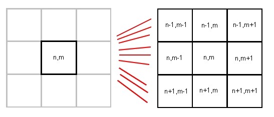
The connections also need to wrap around at the each edges/corners of the grid.
To configure this connection using switches and cases would be extremely arduous and only possible if N and M where known (and small).
We can make this connection using macros. To do this we need to generate macro functions with the following formats (since it must generate 2 values and used to initialize a array of constants)
#define G( X
) something
// NB. G and H could be the same
#define H( Y ) something
#define F( X, Y ) G( X ), H( Y ) // NB. no outer
brackets around the G,H functions
generated code
const Uns elem[2] = { F( e1, e0 ) };
which after macro substitution is equivalent to
const Uns elem[2] = { G( e1 ), H( e0 ) };
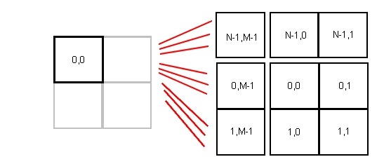
Thus for this example we would define the macros (in ProjectHeader.hpp)
#define N 10
#define M 10
#define Wrap( Xi, X ) ( ((X)+(Xi)) %
(X) )
#define Wrap2( Ni, Mi ) Wrap(
(Ni), (N) ), Wrap( (Mi), (M) )
and use the Wizard to make the following connections
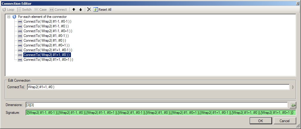
This example shows the use of overriding the dimension field
Calculated Dimension = [9]
User Specified Dimension = [3][3]
This allows the connection access functions to be generated to match the logic of the problem.
Dimensional Circuits
When making connections to objects in circuits that have dimensions, the ConnectTo entries are simply extended to the left to incorporate the circuit dimension. However, when making connections from objects whose parent circuit has dimensions, the values ^#n can be used to extract the element ids of the Circuit.
Eg.
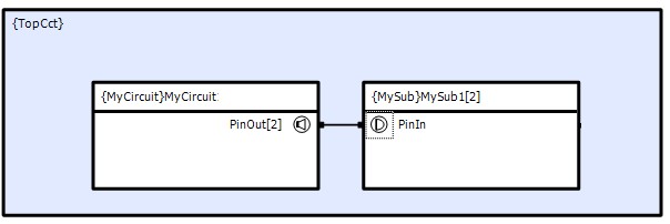
PinIn connects to PinOut. Although PinIn has dimension [1], its parent circuit has dimension [2]. To enable each PinIn to connect to each PinOut, we need to specify ^#0 in the Connect.
Thus
MySub[0]::PinIn connects to MyCircuit::PinOut[0]
MySub[1]::PinIn connects to MyCircuit::PinOut[1]